IntelliLogger™ Data Logger Family Overview
Logic Beach offers a full spectrum of rugged data logger / data acquisition, alarming and reporting instruments that are used world-wide in test and long-term monitoring and reporting applications. IntelliLoggers™ are stand-alone data acquisition instruments that sample input signals, process the readings per a user defined program, assert alarms and store collected data to instrument memory for later download to a PC for plotting and analysis. The IntelliLogger™ data logger line (excluding the IL-Mini) features network connectivity via Ethernet, WiFi and Cellular enabling the instruments to send status/alarm emails, FTP data to servers for unattended data archiving and even support browser access for current reading display, system status and data downloads.
Multi-Channel Programmable Data Loggers…
Logic Beach has a long-standing reputation of providing simple to program, extremely flexible data loggers to meet multitudes of applications. Readings from multiple analog, Modbus and digital sensors and signal sources are all easily handled. Channel count can be increased in the field with the addition of analog and digital expansion modules. Input channels accept a full spectrum of inputs from thermocouples to current to voltage and are simply adapted in the field to different types of signal inputs via software and/or configuration switches for the current application.
Powerful and Intuitive Programming with HyperWare™…
User programming of Logic Beach data acquisition instruments is accomplished using Logic Beach’s revolutionary HyperWare™ icon-based programming and data analysis software. The full-featured, HyperWare™ software supports drag and drop, icon-based programming, numerous communications methods, real-time trending, and collected data plotting and data format conversion. IntelliLogger programs are quickly built by dragging function icons onto the workspace and interconnecting them with a mouse to define program flow. With its intuitive graphic interface, the learning curve is measured in minutes and users quickly become adept at programming IntelliLoggers for their applications. Depending on the user defined program, sampled inputs can be processed by the data logger for statistical data reduction, algebraic manipulation, conditional logging, alarm output, and a variety of other simple to complex functions.
Users employ the rugged IntelliLogger data logging instruments for applications ranging from energy audits to vehicle test, emissions monitoring, product R&D, equipment field test, process improvement, alternative energy monitoring and reporting and countless other applications.
IntelliLogger Models…
Five models of the IntelliLogger™ are offered. All are totally programmable with the powerful HyperWare software. Here is an overview of the model variants:
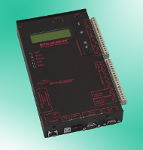
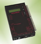
- IL-10: Basic network enabled IntelliLogger. I/O can not be expanded
- IL-20: Same as IL-10 but I/O can be expanded with addition of ILIM-2 and ILIM-7 Expansion Modules
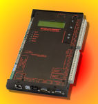
- IL-80: IL-20 with one ILIM-7 Analog Input Expansion Module in a single enclosure
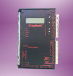
- IL-90: IL-20 with one ILIM-2 Digital Input Expansion Module in a single enclosure
- IL-Mini: Lowest cost fixed I/O logger without network capability.
The following table provides details on differentiating features between the IntelliLogger models.
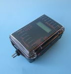
Rugged Remote Site Data Acquisition

IntelliLogger IL-80 shown in optional Enc250 Enclosure with Cellular Data Modem option
IL-10 |
IL-20 |
IL-80 |
IL-90 |
IL-Mini |
|
|---|---|---|---|---|---|
 |
 |
 |
 |
 |
|
| Features: | |||||
| Programmable with HyperWare-II Software | |||||
| HyperWare-II Programming and Communications Software | Nominal Charge | ||||
| Input/Output channel count expandable | |||||
| USB Connectivity | |||||
| Ethernet connectivity | |||||
| -Email, FTP and Web Browser access | |||||
| Cellular Modem connectivity | Optional | Optional | Optional | Optional | No |
| PSTN Modem connectivity | Optional | Optional | Optional | Optional | No |
| WiFi Connectivity | Optional | Optional | Optional | Optional | No |
| Non-licensed Spread Spectrum radio connectivity | Optional | Optional | Optional | Optional | No |
| Weatherproof enclosure | Optional | Optional | Optional | Optional | |
| Non-licensed Spread Spectrum radio connectivity | Optional | Optional | Optional | Optional | Optional |
| Logged Data Memory: |
IL-10 |
IL-20 |
IL-80 |
IL-90 |
IL-Mini |
| Data logging internal memory capacity (Samples) | ~160,000 | ~160,000 | ~160,000 | ~160,000 | ~50,000 |
| -Internal memory expansion available | No | No | No | No | ~160,000 |
| -Memory card for increased/portable data storage | Optional | ||||
| -Memory card memory capacity (Samples) | ~1 million | ~1 million | ~1 million | ~1 million | ~1 million |
| Digital Inputs: |
IL-10 |
IL-20 |
IL-80 |
IL-90 |
IL-Mini |
| Event or Count inputs | 0 | 0 | 0 | 8 | 0 |
| Event, Count or Frequency Input | 4 | 4 | 4 | 4 | 1 |
| Event, Count Inputs or Open Collector Output | 0 | 0 | 0 | 8 | 0 |
| Frequency only inputs | 0 | 0 | 0 | 0 | 2 |
| Digital Input channel expansion with ILIM-2 Modules | No | No | |||
| Non-Isolated Analog Inputs: |
IL-10 |
IL-20 |
IL-80 |
IL-90 |
IL-Mini |
| Fixed range non-isolated analog inputs | 1 | 1 | 1 | 1 | 0 |
| Programmable range non-isolated analog inputs | 2 | 2 | 2 | 2 | 4 |
| -Thermocouple direct input support | Option | ||||
| -Lo-Level (up to 2.2V) Vdc input support | |||||
| -Vdc input, High Level (30V) Vdc input support | No | No | No | No | Option |
| -mAdc input support | Option | ||||
| Non-isolated analog input channel expansion | No | No | No | No | No |
| Isolated Analog Inputs: |
IL-10 |
IL-20 |
IL-80 |
IL-90 |
IL-Mini |
| Isolated Analog Input Channels (User programmable range) | 0 | 0 | 8 | 0 | 0 |
| -Thermocouple direct input | – | – | – | – | |
| -Vdc input | – | – | – | – | |
| -mAdc input | – | – | – | – | |
| Isolated Analog Input expansion with ILIM-7 Modules | No | No | |||
| Outputs: |
IL-10 |
IL-20 |
IL-80 |
IL-90 |
IL-Mini |
| Analog outputs (under program control) | 2 | 2 | 2 | 2 | 0 |
| 5Vdc, 25mA output (under program control) | 1 | 1 | 1 | 2 | 0 |
| Digital output | 2 | 2 | 2 | 2 | 2 (Option) |
| Relay Outputs | 2 | 2 | 2 | 2 | 2 (Option) |
| Open Collector outputs | 0 | 0 | 0 | 3 | 0 |
| Digital output expansion with ILIM-2 Modules | No | No | |||
| Modbus Communication: |
IL-10 |
IL-20 |
IL-80 |
IL-90 |
IL-Mini |
| Modbus RTU Master | Option | Option | Option | Option | Option |
| Modbus RTU Slave | Option | Option | Option | Option | Option |
| Modbus TCP Server | Option | Option | Option | Option | Option |